2024 SCTC and IEPC Debrief

This article is a “trip report” from two back-to-back conferences held over the last two weeks in Southern France. The first week was in Avignon for the 17th Spacecraft Charging Technology Conference (SCTC). Then the following week, I (LB) headed on a train over to Toulouse for the 38th International Electric Propulsion Conference (IEPC).
17th Spacecraft Charging Technology Conference (SCTC)
This was my first time in Avignon, and also my first time to SCTC in person. I attended the prior 2022 installment virtually to present preliminary results form an experimental and numerical investigation of lunar dust regolith adhesion onto spacesuits. That work was later cleaned up into a special issue journal paper: Brieda, L., Helou, E., Wang, J. “Toward modeling of charged dust dynamic at mesoscale resolution”, Trans. Plasma Science, Vol. 51, No. 9, 2023 (10.1109/TPS.2023.3285151). This is a project I started working on with a University of Southern California Department of Astronautical Engineering (where I teach) Ph.D. student Elana Helou and her (and my from Virginia Tech M.Sc.) advisor Joe Wang. The goal of this research is to obtain insight into how lunar regolith grains become embedded in the Orthofabric material making up the outer layer of legacy astronaut space suits. Regolith is known to introduce difficulties for any envisioned human lunar exploration due to its fine size, rough surface morphology, and propensity to build up surface charge which make it easily stuck to any objects it comes in contact with. Regolith grains can become easily embedded between the cloth fibers. Brushing, shaking, and even applications of compressed air are not effective at removing all grains. One can thus envision that after several moonwalks, astronaut spacesuits become rendered unusable (or will require the use of some kind of laundering facilities) due to the cumulative build up of regolith. We later reported on an experimental high speed camera characterization of regolith simulant fallout under atmospheric conditions at the 2023 Applied Space Environments Conference (ASEC). In that work, we also exposed the sample to plasma in our vacuum chamber. You will find more information on this in a separate blog post titled Dust Dynamics at Mesoscale Resolution.
At this conference, my objective was to describe a new modeling capability I have been incorporating into the Contamination Transport Simulation Program (CTSP). Particle tracing codes, like CTSP or even my legacy plasma code Draco (thesis), use simulation particles to represent the gas population, and a surface mesh to represent the embedded objects. Surface impact is checked by performing line-triangle intersection tests against the tessellated geometry. In order to maintain reasonable run times, it is necessary to reduce the subset of triangles to check against to just those that could potentially be hit (i.e. those within the bounding box of the trajectory segment traveled during a single time step). There are various approaches available here, but they generally require storing the surface mesh in some data structure capable of looking up just the nearby triangles. Draco used “interface” Cartesian mesh cells to store a list of triangles cutting through them. CTSP stores triangles in an octree linearized by the Morton Z-order space filling curve. As one may imagine, building these data structures takes some time, since all of the possibly hundreds of thousands of surface elements need to be sorted into the appropriate containers. This makes it impractical for the simulation to consider moving surfaces, since rebuilding the container at every time step would be too time consuming. However such dynamism is exactly what I was after. The goal is to develop modeling capability for simulating rarefied gas flow (i.e. using the PIC or DSMC method) interacting with moving surfaces. Specifically in this case, I wanted to model ambient plasma, let’s say from solar wind, impinging onto a spacesuit coated with regolith grains in which each grain is represented by a surface mesh. The impinging ions are envisioned to deposit charge to the grains, which will then lead to lofting.
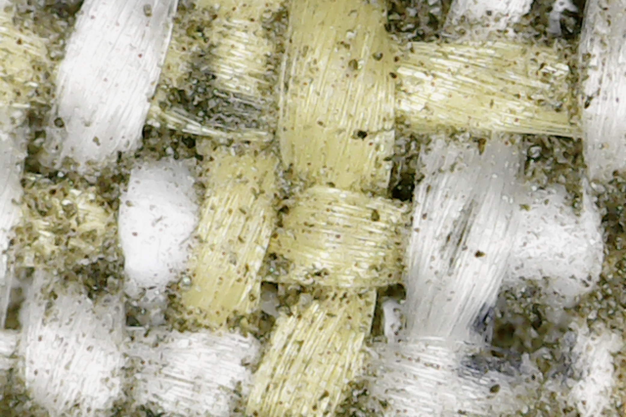
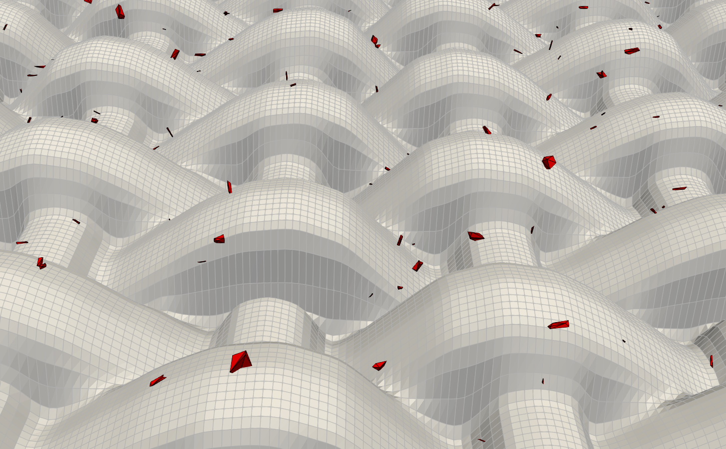
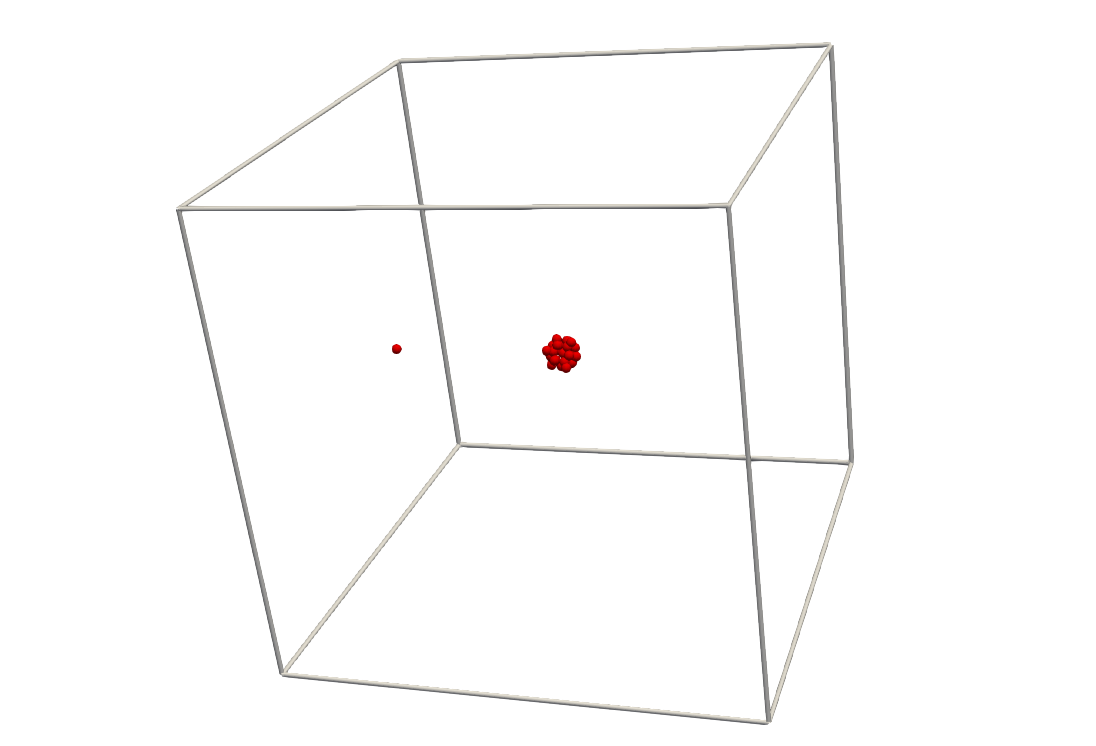
Figure 1 illustrates the envisioned initial setup. In the first picture you can see a microscope image of our spacesuit sample coated with JSC-1a lunar simulant. The second picture shows the fabric mesh (to data, will improve in the future to capture the individual strands…) with several random grain surfaces loaded on top of it. These are created through a very simplistic “rock generator” module incorporated into CTSP. The grains are loaded by dropping them from a virtual plane located above the fabric. They then fall until hitting the fabric. Next, a plasma source is initiated from a smaller virtual plane, as shown in Figure 2.
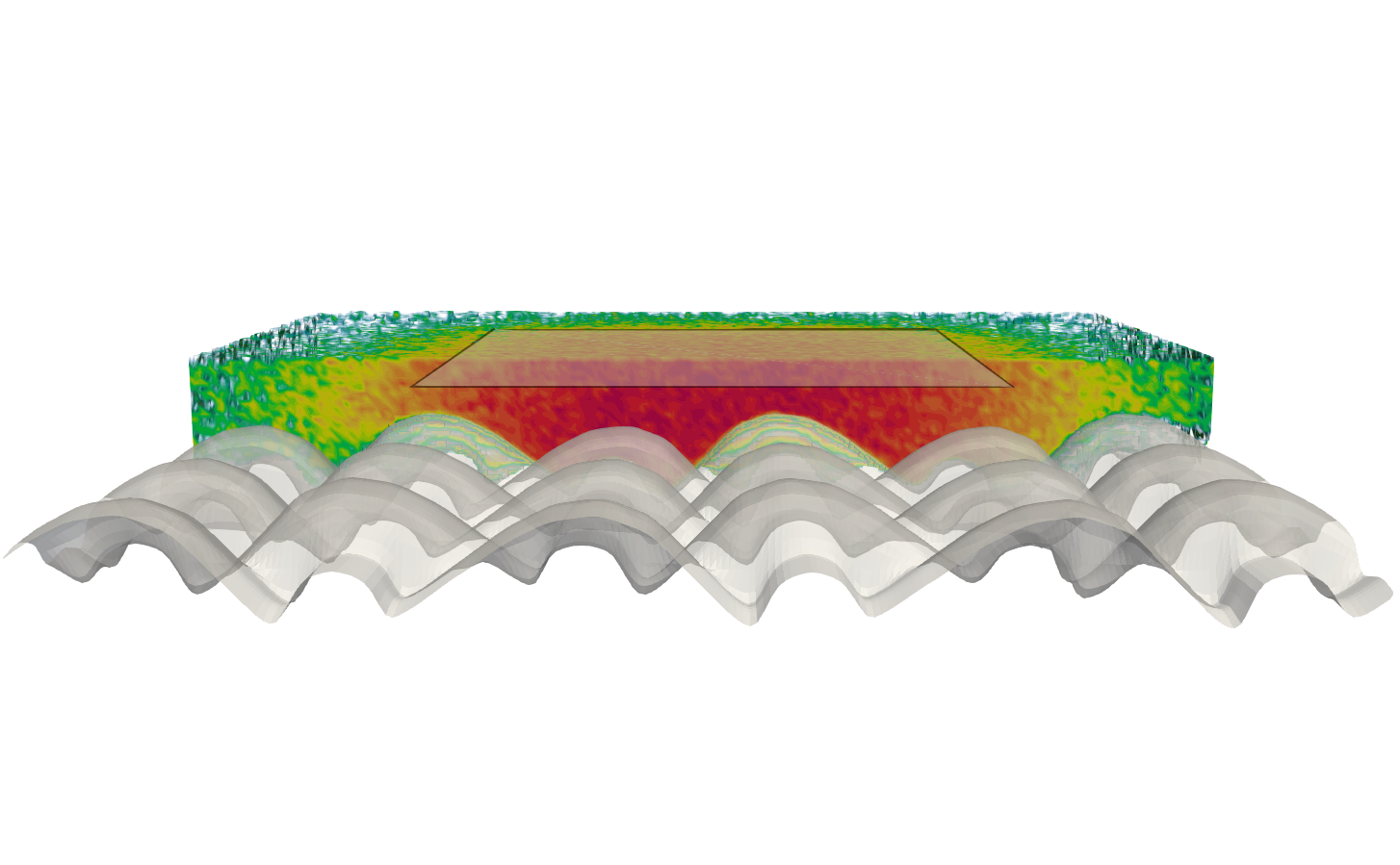
The impinging plasma particles deposit charge to the contacted surface element. At this time, all surfaces are assumed to be perfect insulators: there is no charge redistribution. Initially, the plasma beam is made to have a net positive charge. As such,
both the regolith grains and the substrate charge up positively. Charge on each surface element is used to compute the Coulomb force with other near-by surface elements. This force is then applied through the center of mass (i.e. there is no tumbling implemented yet), leading to the lofting of the dust grains. You can see this neat – if not yet physical (the surface adhesion force model needs more work) – result in the videos in Figure 3.
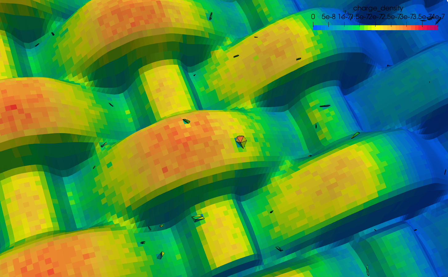
The top down view in the second animation lets you notice the charge shadow left behind by the lofted grain. The plasma beam was switched off around third of the way through the simulation, which explains why the charge in these shadow regions does not change. Another view of surface charge is plotted in Figure 4.
So how does all this work? Well more details will be provided in an upcoming paper, but essentially, surface geometry is represented by a collection of individual surface “actors”. This is what I am calling each individual surface object, which itself can consist of multiple surface zones. The legacy CTSP code supported just a single surface. In this particular simulation, the fabric mesh is one surface, and separate surfaces get created for each randomly generated surface grain. The input file reads as follows:
# load fabric mesh into surface called "fabric"
surface_load_obj{file_name:"shrinkwrap/fabric.obj",surface_name:fabric, units:cm}

# generate bunch of random grains, each loaded into a unique surface with names grain_001, etc.
load_grains{comps:aplatel, mat:regolith, prefix:grain, shape:rock, h_range:[0.0008,0.0008], size_range:[50e-6,200e-6], ar_range:[1,10.0], vel_range:[0.0,0.0], num_grains: 250}
The simulation then creates a unique octree for each surface. In order to model dynamics – without needing to redo the tree – the code uses transformation matrices to map from global to local (surface) coordinate frame. Translating or rotating a shape then thus requires only updating the transformation matrix. This process does increase the computational overhead since for each particle hit impact, we need to compute \(\vec{x}_{loc} = \mathbf{A}_{glob\to loc} \vec{x}_{glob}\), however this is presumably much faster than redoing the octree at every time step (especially since matrix-vector multiplication is something that can be readily optimized and parallelized).
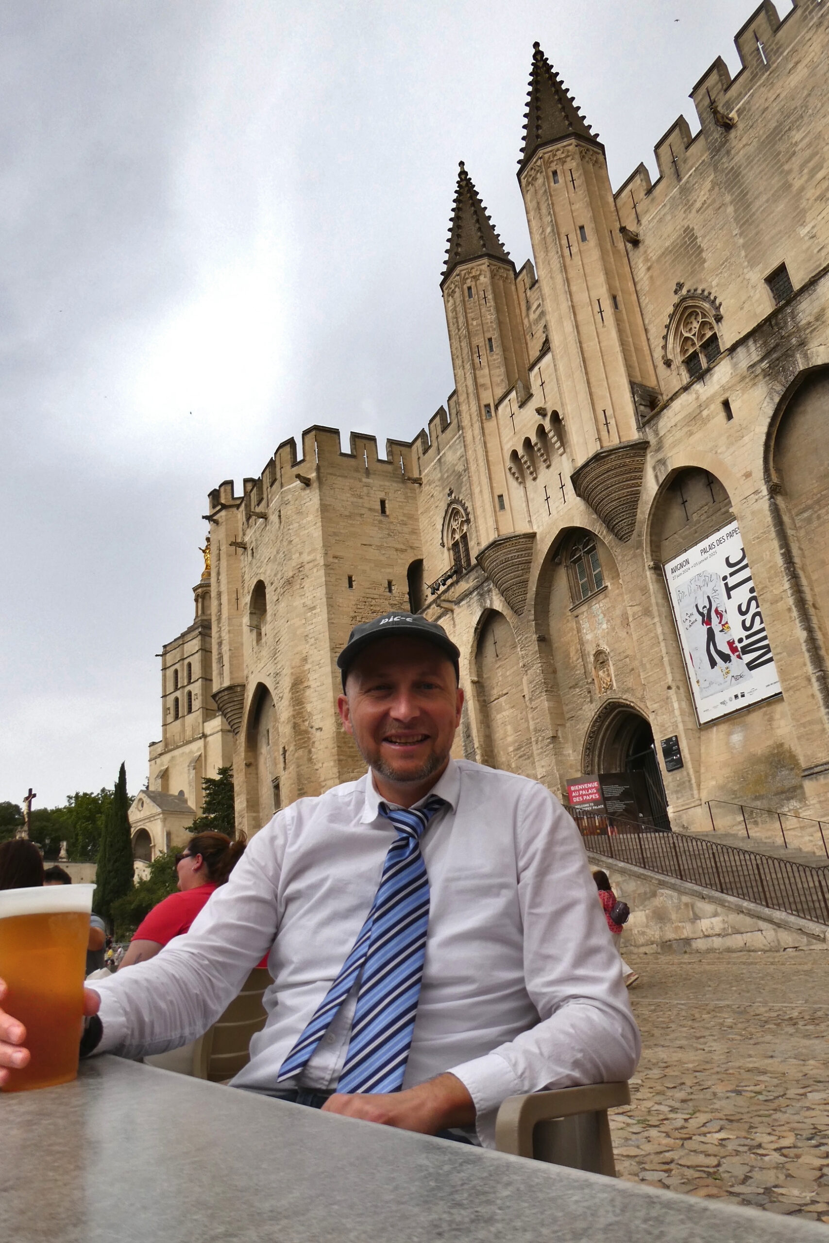
Now what about the rest of the conference? I very much enjoyed SCTC. One highlight was running into a former student of mine, Nick C.. Nick now works at Space-X, and was cleared to present fascinating paper correlating charging events Space-X observed on their Starlink constellation to the so-called Appleton anomaly (a region of increased plasma density). I will have more pictures from this conference on my personal site, but in the meantime, here is a picture of me enjoying a beer in front of the Palais des Papes. This palace served as the papal residence during the 14th century, and in 2024, became the SCTC conference venue.
38th International Electric Propulsion Conference (IEPC)
After a week in Avignon, it was time to head over to Toulouse for IEPC on a direct train through Narbonne. I was already familiar with Toulouse from the 4th European Contamination Workshop held the previous Fall. Toulouse is a the French aerospace capital, and is home to labs and companies such as CNES, ONERA, Airbus, Safran, Thales Alenia, and many others. This was my first IEPC since Vienna in 2019, and my first time presenting since 2017 at Georgia Tech. I ended up pulling my 2019 paper. This time, I had three.
Asperia Thruster
Besides getting to catch up with old acquaintances, what I was the most excited about was introducing four ASPEN students Olivia, Emily, Kayden, and Max, to the IEPC community. As noted in a prior post, for the two years, I have been co-advising a (primarily) undergraduate student club at USC called ASPEN (Advanced Spacecraft Propulsion and ENergy). This club was originally founded by Matt Gilpin, with students historically focusing on components for a nuclear thermal rocket. I proposed a new idea to develop a single-burn solid fuel “plasma rocket” for deorbiting Cubesats or for providing orbital maneuvering capability. The benefit of this project is that it some compatible with hands-on experimentation that provides the university students experience working with vacuum chambers and plasmas, which are skills in high demand from various aerospace and fusion energy companies. The thruster uses Adamantane (C10H16) for fuel. This hydrocarbon exists as a solid crystalline substance at ambient conditions, but readily sublimates under exposure to vacuum without the need for a catalyst bed. It also has a higher ionization cross-section than Xenon, while having nearly identical mass (136 vs. 131.3 amu). The thruster – essentially a simple ion gun – is envisioned to store the propellant in a hermetically sealed tank. Once needed, a membrane is punctured (details of this step are still TBD), allowing the molecules to sublimate into an ionization chamber consisting of two parallel electrodes with a high (~1kV) voltage drop applied between them. The field-emitted electrons ionize the propellant which is then expelled through a central opening in the cathode. Simple. ASPEN presented their initial design at the 2023 Gaseous Electronics Conference (GEC) at University of Michigan. This time, they traveled to a much larger venue to give an update.
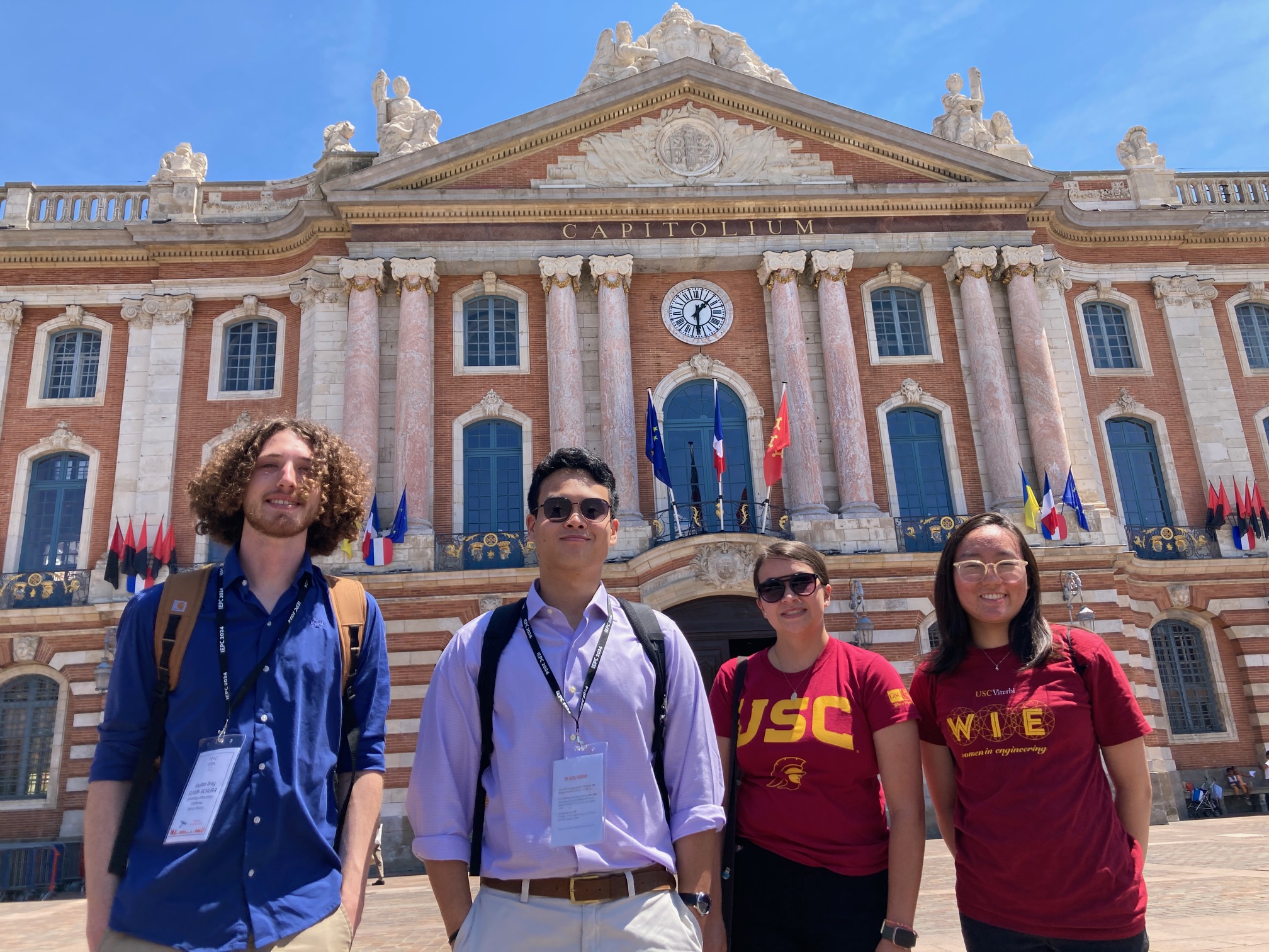
Figure 6 shows the “IEPC 2024” version of the the thruster. This version is 3D printed, unlike the very much DIY model at GEC. The first picture shows in placed in the vacuum chamber, while the second version has it operating. We tested this thruster at both rough vacuum and at high vacuum, although most testing was done at rough vacuum to maximize testing during the limited “build hour”.
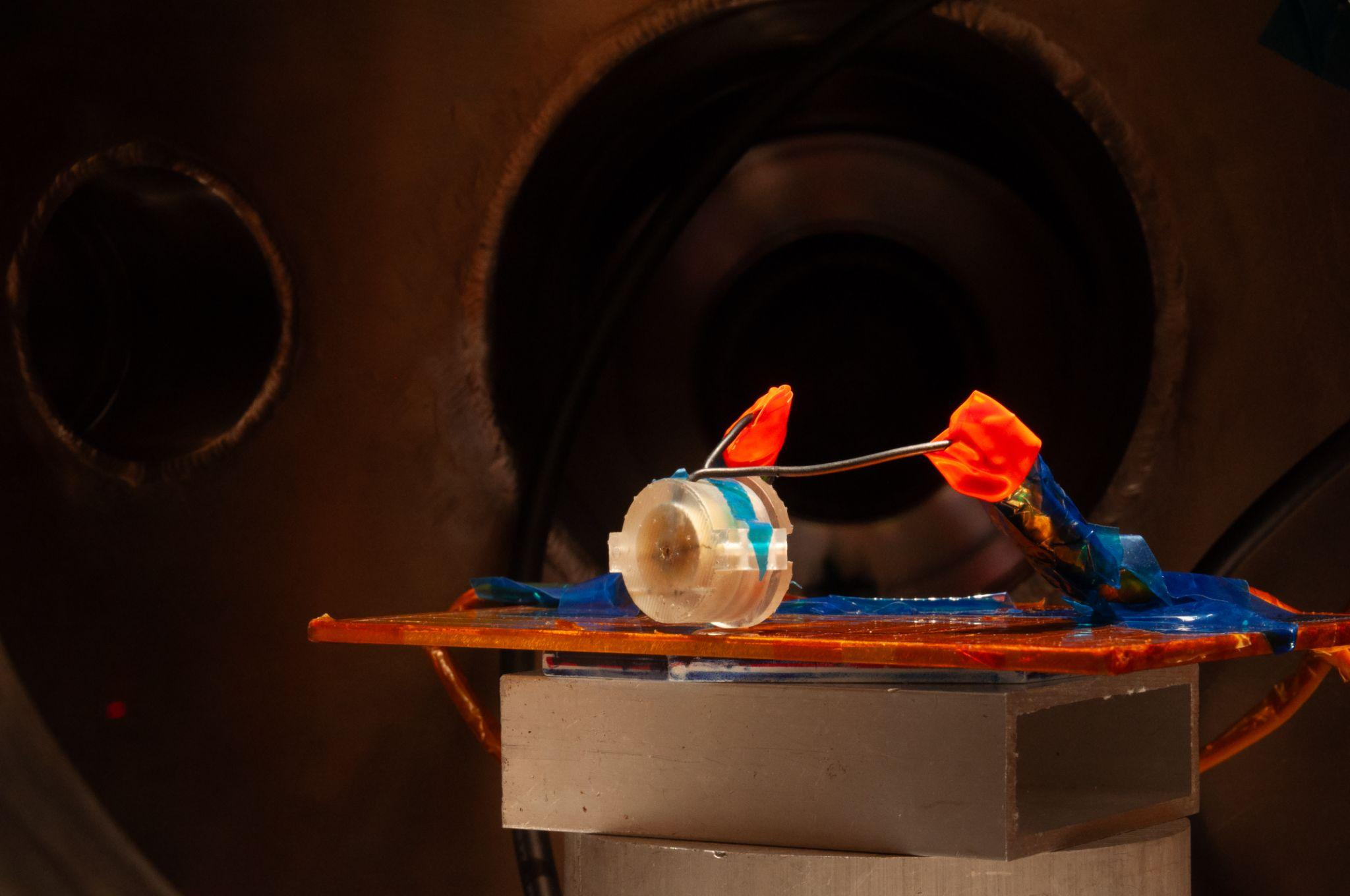
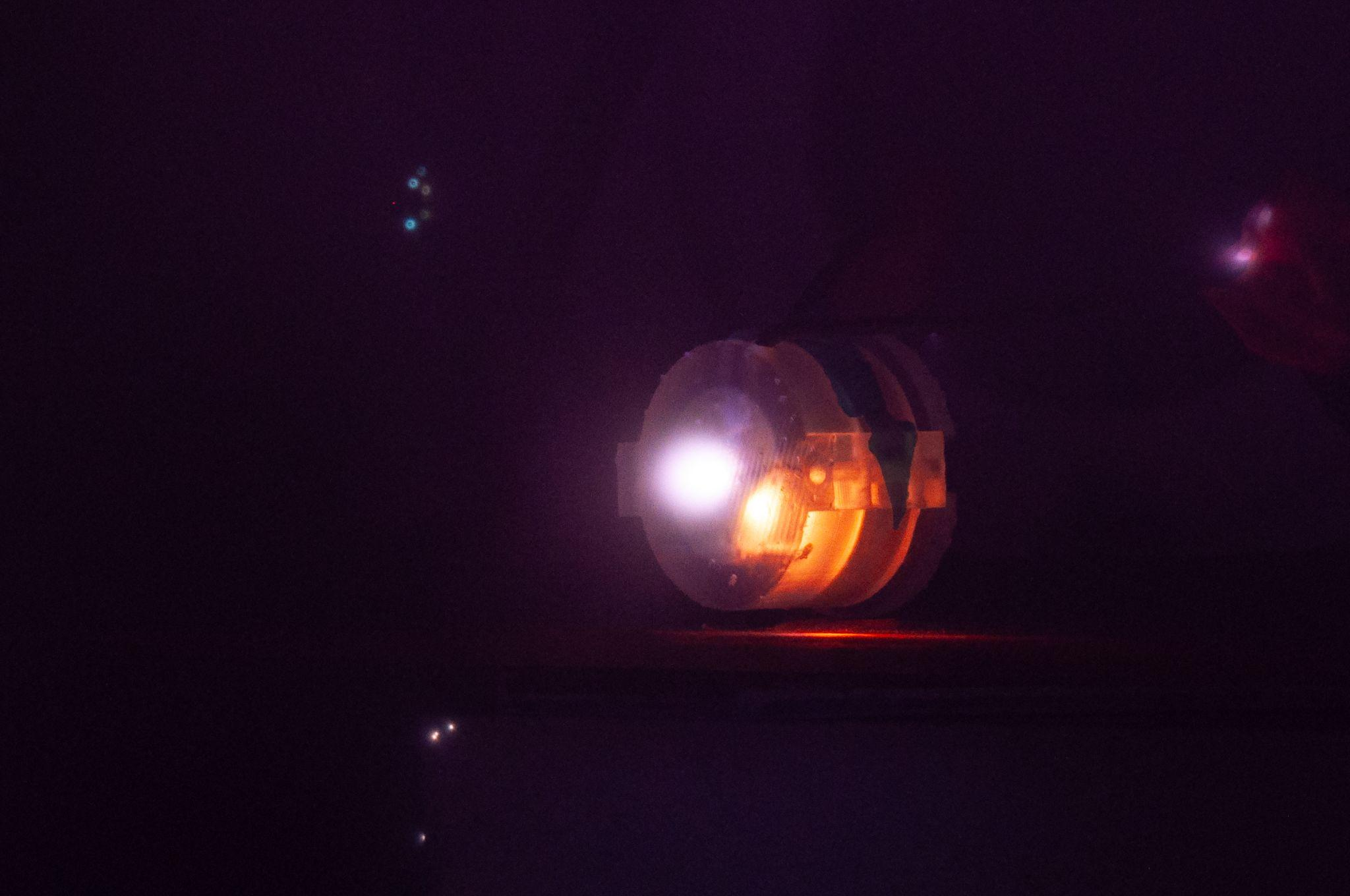
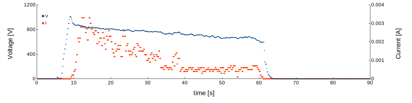
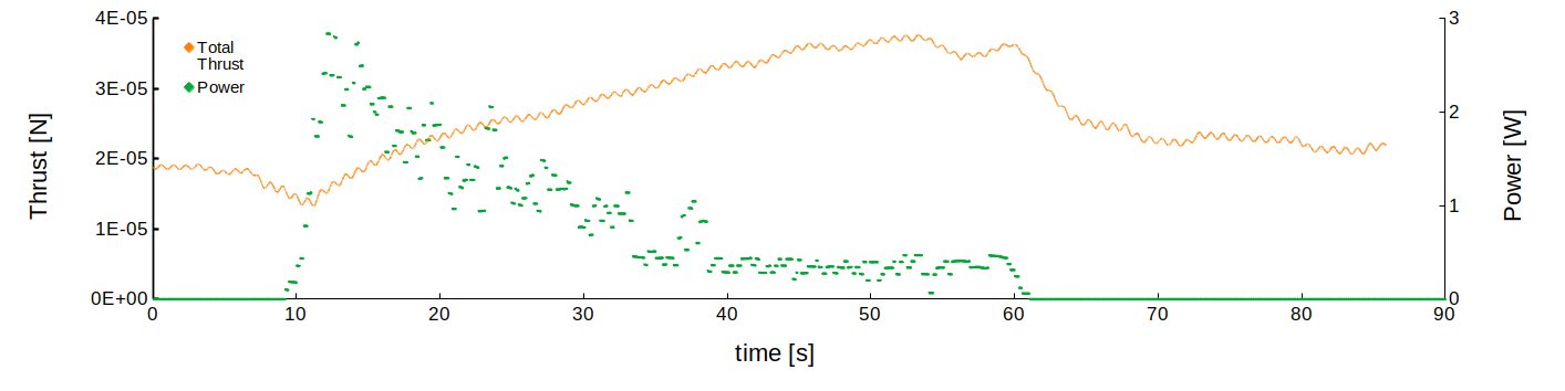
Figure 7 shows the thrust, power, voltage, and current for a typical burn. While some initial work has been completed on designing a thrust stand, these thrust measurements were made by observing displacement of a suspended pendulum using a laser system. We can see that while the applied voltage is near a kV, the total power is only around 1 W, making the device readily compatible with low power systems like Cubesats.
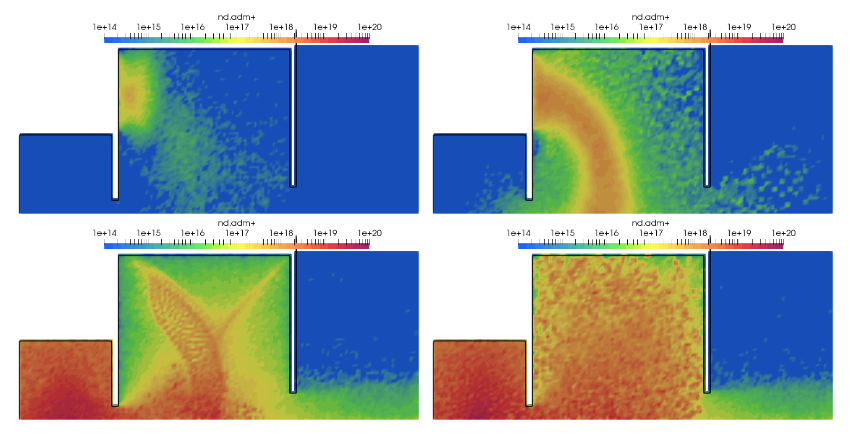
In addition to the lab experiments, ASPEN students also started working on numerical simulations. Here I aided by setting up and running several Starfish simulations to compare plasma dynamics at different geometrical configurations, while Emily learned how to use LAMMPS to run initial simulations of Adamantane fragmentation. These modeling tasks remain as work in progress that will be tackled during the 2024-2025 academic year. Modeling effort will be used to optimize the hardware design in order to develop a flight prototype.
To read more, take a look at the paper, Kukar, O., et. al.,”Design and Characterization of an Adamantane Thruster for Cubesat Applications”>, IEPC-2024-163.
CAD PIC
I also gave an update on my current effort to develop a Particle in Cell (PIC) simulation code operating directly with CAD geometries. This effort stems from a 2022 NASA SBIR Phase I grant to develop such capability for contamination modeling studies, as described in this prior post. My goal for this conference was to have a demo PIC code available, but I simply ran out of time, so this presentation ended up being more of a briefing on the work to date. This thus remains future work for now.
Hall Thruster Pulsed Mode
The paper that I was the most excited about, presentation wise, was “Experimental Characterization of SPT-100 Hall Effect
Thruster Operating in a Pulsed Mode”, IEPC-2024-137. Being a modeler, it was fascinating to put out a solely experimental paper! This paper describes an experiment I got a chance to run at the Air Force Research Lab at Edwards AFB, in which we ran the SPT-100 Hall effect thruster in a “pulsed mode”. This experiment was usedto validate the numerically-derived proposal from our 2021 JAP paper “Quasi-steady testing approach for high‐power Hall thrusters”, 10.1063/5.0067232. Essentially the idea is that as Hall thruster power levels increase, it becomes challenging, if not outright impossible, to find facilities with sufficiently high pumping speed to operate the thrusters at acceptable background pressure (generally no more than 1e-5 Torr). However, one possibility could be running the thruster in a pulsed mode. The anode flow is then cycled between nominal and a reduced state. All other control points, including magnet current, discharge voltage, and cathode flow rates, remain fixed. The anode flow rate is dropped as much as possible without distinguishing the discharge. The full flow is then established, and since all other controllers are already at their nominal states, the discharge can be expected to recover to its nominal state quite rapidly. One may then rapidly obtain measurements of plume properties or the device thrust before these quantities become strongly affected by the background pressure. At least that was what simulations suggested. In this experiment, we got to replicate this idea, and surprisingly, the experimental observations actually agreed with the simulation predictions.
Figure 9 below shows the experimental setup. As you can see, Faraday, Langmuir, and RPA probes were placed in the plume of the thruster. These probes were placed on a stationary stage and thus data was collected only at a single point. A camera placed at the chamber window was used to record the plume discharge. Pressure and RGA probes were located in the chamber wall in order to characterize the background population.
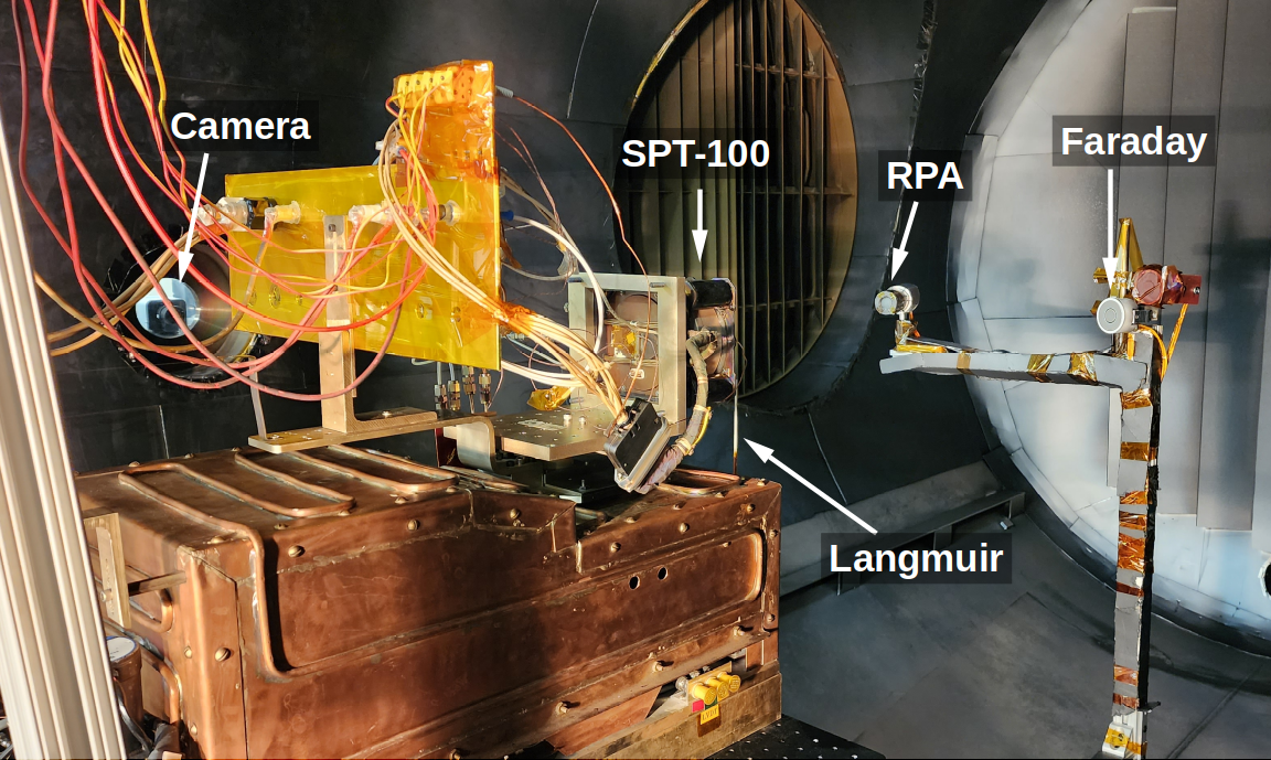
Figure 10 illustrates the data captured by the camera. Transition to the low-flow mode begins at time 0. We can see that the plume becomes glow-like, with the central jet disappearing. Transition back to the nominal state begins at minute 7.
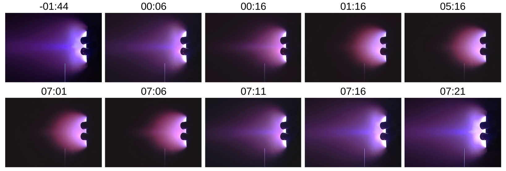
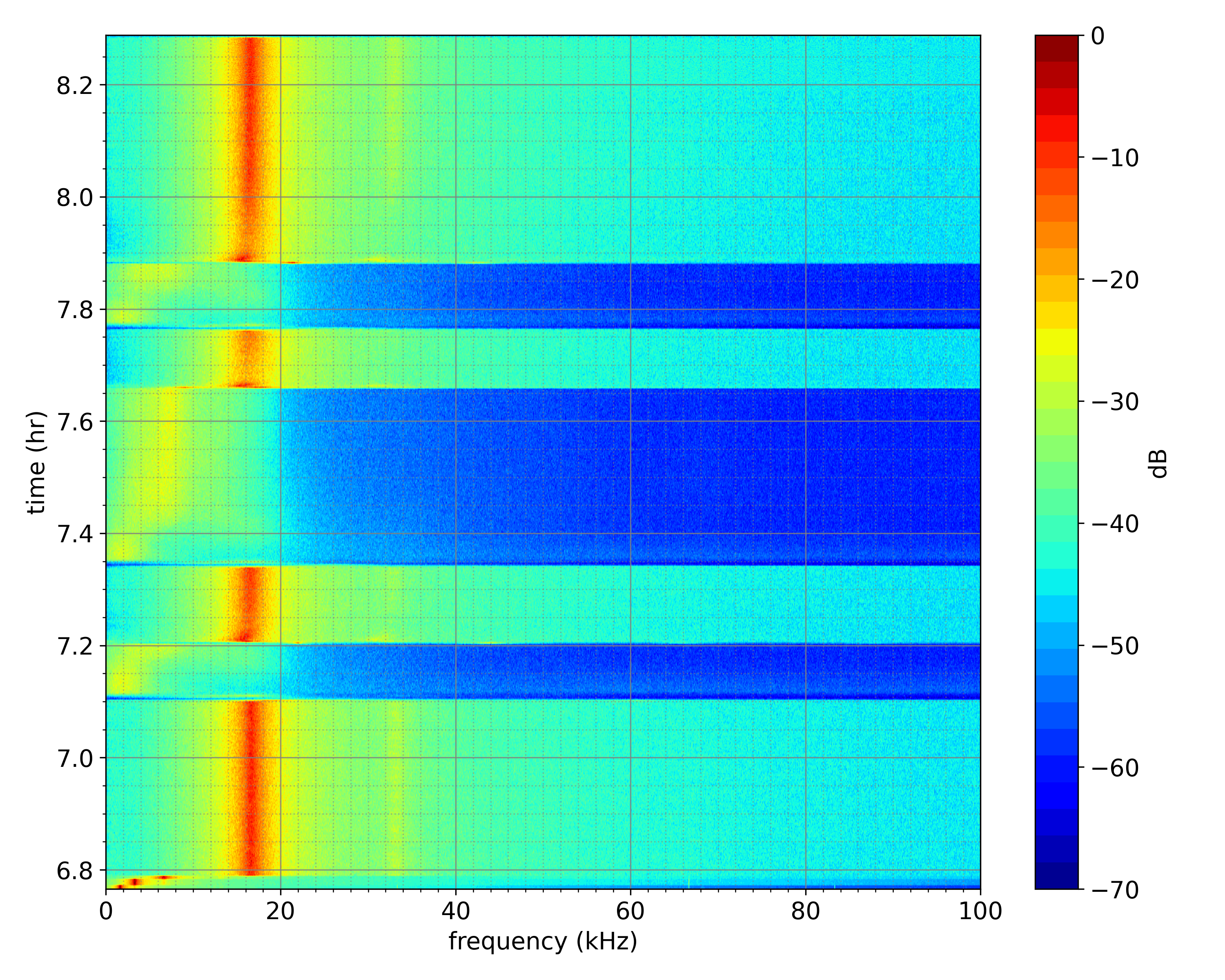
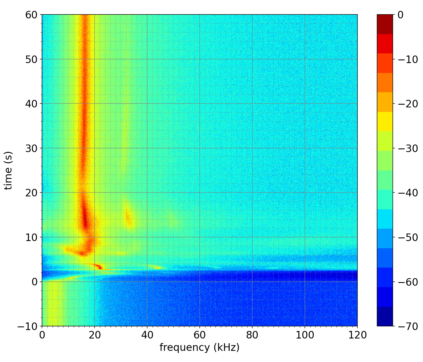
Figure 11 shows what I was really after: the temporal variation in discharge current. We can see a clearly defined breathing mode at around 17 kHz during the nominal set points. It disappears once the anode flow is reduced and the thruster transitions to the glow discharge mode. The second picture is a zoom in onto one of these transitions. As an aside, processing this data gave me new respect for experimentalists! We ended up with almost 500 Gb of data from 3 days of testing with a good part of that time spent debugging the data acquisition system settings to allow it to collect such huge amounts of data without crashing due to buffer overruns.
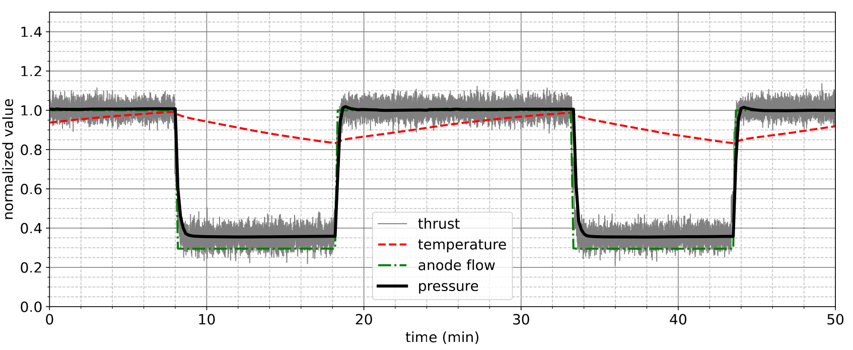
Finally, Figure 12 highlights the temporal variation in thrust, chamber pressure, and thruster temperature. We can notice that thruster temperature does not seem to have a noticeable impact on the device performance at least within the variation observed here. More importantly, we can note that the nominal thrust is achieved on time scales comparable to pressure increase. There are many more plots in the paper, including read outs from the RPA and Langmuir probe, so I recommend you take a look there. I am also currently working on cleaning up write up and the Langmuir probe data, for a journal submission.
Journal of Electric Propulsion Special Issue
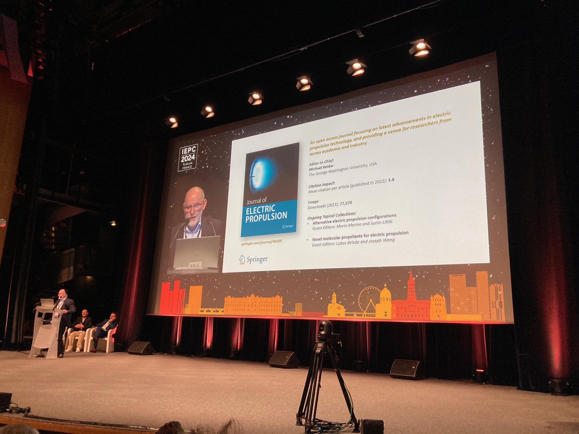
Speaking of journals, I, along with Prof. Joe Wang from USC, are currently editing a Journal of Electric Propulsion (JEP) special issue on molecular propellants. The submission deadline is December 31st, 2024 so please submit an article if you are working in this field. We are interested in papers on any, experimental or numerical, use or investigation of non-atomic propellants for plasma propulsion applications. The picture below shows Prof. Michael Keidar introducing this special issue during his opening remarks.
Expo Booth
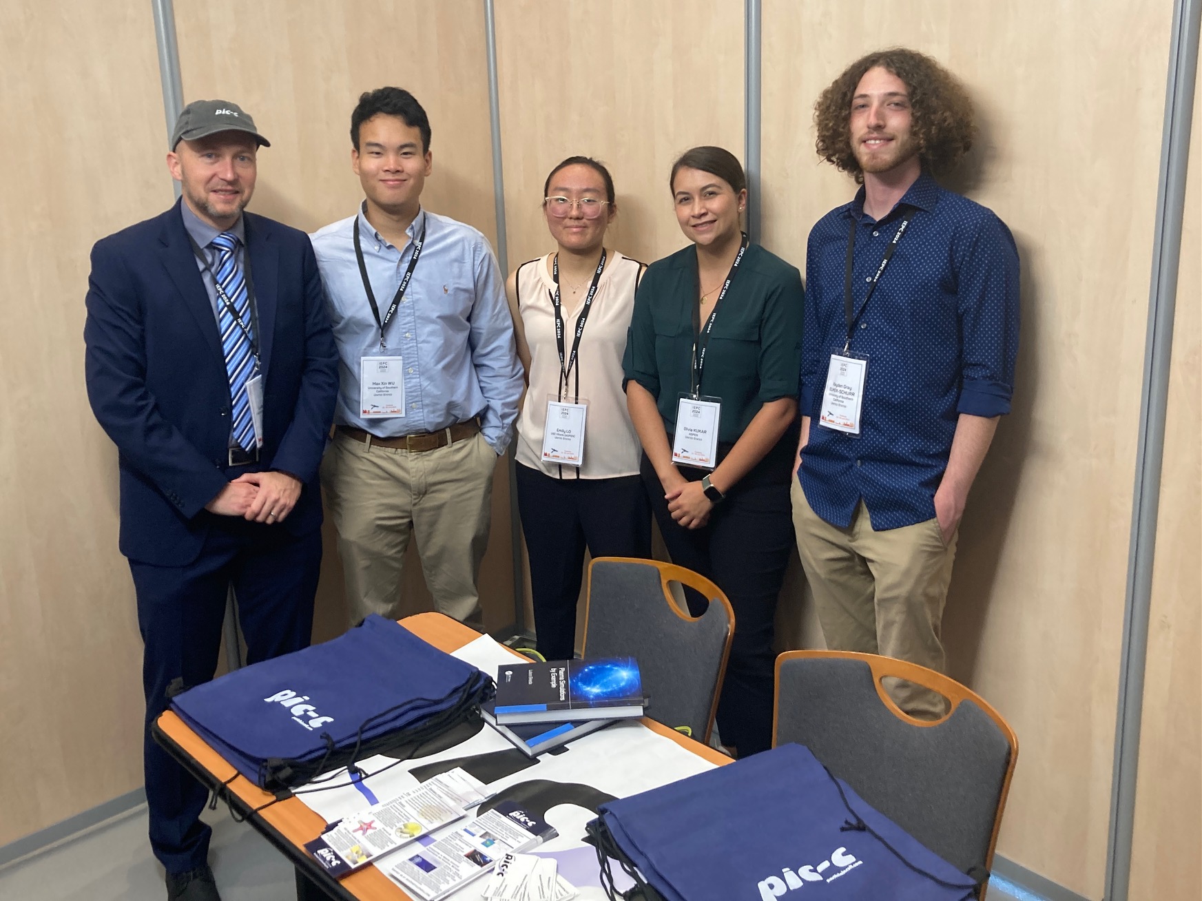
As a final note, I had a booth at this IEPC due to PIC-C being one of the conference sponsors. First, my gratitude goes to the four ASPEN students for helping to staff the booth so that I can go sneak way to see talks. Secondly, thank you to all who stopped by. Not wanting to toot my own horn, but it was actually really amazing – and unexpected – have so many of you come introduce yourselves and report that you found either this blog, my plasma simulations classes, or the book (buy here), useful in your studies. If you don’t mind sharing a testimonial, please leave a comment below or shoot me an email.