Monte Carlo Collisions (MCC) Example

Introduction
The two primary drivers that control movement of individual particles in plasmas are the electric field and the inter-particle collisions. MCC (Monte Carlo Collisions) is a simple method for modeling particle collisions. It can be coupled with the PIC method to obtain the PIC-MCC algorithm. MCC works by looping through all source particles, testing each particle for a collision, and if a collision occurs, performing the appropriate action. It differs from the commonly used DSMC (Direct Simulation Monte Carlo) in that in the MCC method, the source particles are collided with a target “cloud”. In DSMC both the source and the target are actual simulation particles. This allows DSMC to conserve energy and momentum through the collision. Since in MCC there is no target particle, energy is not conserved unless some non-standard adjustments are made to the background population.
MCC Applications
Does this mean that MCC is not physically sound and should not be used? Not really. In many scenarios, the density of the target is many orders of magnitude greater than the density of the source species. If the collision frequency is not particularly high, it is reasonable to assume that the target species is affect by collisions to such a small extend as to be negligible. The benefit of MCC over DSMC is that MCC is much simpler to implement. MCC is also much faster since particle pairs do not need to be selected. In this sense, MCC is analogous to the Finite Difference Method. It is quite limited compared to the Finite Volume, however, in applications where it works, it works great.
And one application where MCC works is in modeling the charge exchange (CEX) process in electric propulsion thruster plumes. To illustrate this, let’s consider the typical 30 cm ion thruster. The neutral density near the thruster exit is approximately 1018 m-3 while the density of the ion beam is around 1016 m-3. These values come from Roy.
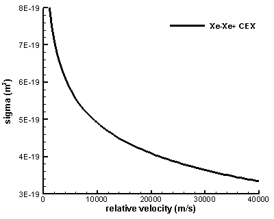
The collision cross-section for CEX in Xenon is given by Rapp and Francis (as stated in Roy) as \(\sigma_{CEX}=(k_1\ln g+k_2)^2\cdot 10^{-20}\text{m}^2\) where k1=-0.8821 and k2=15.1262. This cross-section is plotted below in Figure 1 for the range of velocities encountered in EP applications. As we can see, the cross-section decreases with an increase in the relative velocity. Ion thrusters have an Isp (specific impulse) of around 3,000 seconds, which translates to exit velocities of 29,000 m/s. The neutral particles are moving at their thermal velocity since they are not accelerated through a nozzle as is done in a conventional chemical rocket. The thermal velocity for Xenon at 1000K is \(v_{th}=\sqrt{2kT/m}=356\,\text{m/s}\). Since this speed is significantly smaller than the speed at which ions travel, we can ignore it, and let the relative velocity be completely determined by ions. The cross-section for 29,000 m/s is \(3.67\times10^{-19}\,\text{m}^2\).
Next let’s consider the area near the exit of the thruster in which the neutral density is large enough for the collisions to happen. Let’s assume that neutrals are concentrated in a cylinder, and that the length of the cylinder is four thruster radii (4*15cm). The percentage of ions that will pass through this cylinder without colliding with a neutral atom is \(1-n_n\sigma L=0.78\). In other words, 22% of ions will collide. Since an ion-neutral pair is required for the collision, the number density of neutrals involved in a CEX collision is 0.11*1e16 = 2.2e15 #/m3. This represents only 0.22% of the neutral population. Hence, it is safe to assume that the overall impact on the neutral population from CEX collisions is negligible, and that MCC can be used. By the way, this collision rate actually over-estimates reality, since we did not take into account the r2 decrease in neutral population density.

Figure 1. The Rapp and Francis collision cross-section for Xenon charge exchange
The MCC Method
To use the MCC method, we first need to loop through all source particle. For each particle we calculate the collision probability. This probability is then compared to a random number. If the probability is larger than the random number, the collision occurs and a process-specific collision handler is called. The collision probability is given by Birdsall as
$$P=1-\exp\left(-\nu \Delta t\right) = 1-\exp\left(-n_n\sigma g \Delta t\right)$$
In this expression, nn is the density of the target gas at the location of the particle, σ is the collision cross-section, g is the relative velocity, and Δt is the time difference between collision checks. This time step may correspond to the time step used to move the ions in the PIC method. However, often it is preferred to call the collision handler at a reduced frequency to reduce numerical errors and to also improve code performance.
To model the CEX process, we simply replace the velocities of the collided ion with random values obtained by sampling the Maxwellian distribution at the neutral temperature, \(v_{new}=v_{th,n}f_{M}\). Birdsall provides a neat way for sampling the Maxwellian given by
$$f_M= \left(\displaystyle\sum_{i=1}^{M}R_i-\frac{M}{2}\right)\left(\displaystyle \frac{M}{12}\right)^{-1/2}$$
where R is a random number. In our implementation we use M=3, which gives us \(f_M=2\left(R+R+R-1.5\right)\)
MCC Example
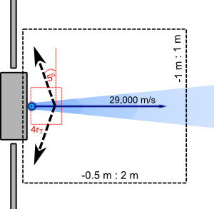
We can illustrate the MCC method with a simple example. The simulation concept is sketched in the figure below, where the black box corresponds to our computational domain. We inject ion particles from the thruster with the axial velocity of 29,000 m/s and a small random radial component (± 2000 m/s). In this example we are are not particularly concerned about the physical number density of ions, since we are not solving electric potential. We also don’t directly simulate the neutral atoms. Instead we prescribe an analytical density profile. This is a common practice in EP plume modeling, since the neutral gas can be described accurately using analytical models. The result is a significant improvement in code performance and a decrease in memory requirements. We prescribe the analytical plume profile from equation 3.17 in Roy’s dissertation,
$$n_n = n_{n0}a\left[1-\left\{1+\left(\frac{r_T}{R}\right)^2\right\}^{-1/2}\right]\cos \theta$$
where \(a=[1-1/\sqrt{2}]^{-1}\) is a correction factor, \(R=[r^2+(z+r_T)^2]^{1/2}\), and \(\theta=\tan^{-1}[r/(z+r_T)]\). This equation is derived for a plume effusing from a point source located one thruster radius upstream of the thruster exit plane, hence the rT factor. Note, this formulation is slightly modified from the expression given by Roy. His equation includes an additional 1/2 factor since his neutral density corresponds to the reservoir density, which happens to be twice the density at the thruster exit.

Figure 2. Schematic of the simulation domain. The black box corresponds to our simulation domain. The fixed electric field is applied at distances less than 4 thruster radii from the thruster exit.
To keep the example simple, we neglect the self-consistent calculation of electric field and instead prescribe a fixed field. The strength of the electric field is 50 V/m and acts 5o off the axis normal. The field acts only within axial location less than 4 thruster radii from the thruster exit. This electric field is a somewhat crude approximation of what happens in a real electric propulsion plume. The small electric field that develops is due to the radial expansion of the plume and the associated density drop. This potential drop is generally only few Volts and acts across distances corresponding to the plume radius.

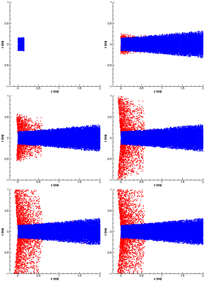
Figure 3. Simulation results. The blue particles are the un-collided ions, while the red squares are particles that have undergone CEX collision. Tecplot was used to create the AVI movie which was then converted to an animated GIF.
You can see the simulation results in Figure 3 above. In this plot the blue squares correspond to ions that have not undergone a collision. The red squares are the CEX ions. We can see that although the electric field acts on both the blue and the red ions, the beam ions (blue) are not perturbed by it. This is the expected behavior. However, the CEX ions are born with a slow thermal velocity, and as such are strongly affected by the electric field. Since this electric field acts in the radial direction, the CEX ions are accelerated out of the plume. They then form the CEX wing structure that was discussed in the previous article. Formation of this structure is clearly visible in these results. The density of the CEX wing is greater near the thruster exit due to the higher neutral density and hence higher collision frequency. As you can see, the backflow of charged particles from electric propulsion plumes is a real issue. Even if a sensitive instrument is place outside the main plasma beam, the local plasma environment around the instrument may still be strongly influenced by thruster operations.
Multiple Collision Types
Finally, a little aside. It is possible to model other collision types using MCC. MCC is well suited for ionization collisions, and also for scattering (momentum transfer) of electrons off of neutrals, among others. Basically, MCC works well when the target species is much denser or heavier than the source. MCC works relatively well for all EP plume type collisions except for momentum transfer between like species (such as neutral-neutral collisions). If you include multiple collision types, the collision cross-section used to calculate the collision probability is the sum of all individual cross-sections. Then, if the collision occurs, the code needs to select another random number to determine which collision process occurred. This selection is based on the rates of the individual cross-sections to the sum, and is selected by determining which bin the random number fell in to.
Java Implementation
The MCC example is implemented in Java in mcc.java. The code consists of an extremely simplified particle push algorithm. A computational mesh is not used since we are not solving the electric potential and neutral density is calculated analytically. Particles are represented by a class called Particle. The Particle class contains several functions to update particle positions, and also to collide a particle. The collision code is called from the loop in CollideParticles(). This is the main driver for the collision process. It loops through all particles and for each calls the MCC collision algorithm, collideMCC().
/*loops through particles and calls the MCC algorith for each*/
void CollideParticles()
{
	Iterator iterator = particles.iterator();
	while(iterator.hasNext())
	{
		Particle part = (Particle)iterator.next();
		part.collideMCC(dt);
	}
}
The actual MCC algorithm is implemented in the collideMCC method of the Particle class. The function first determines the neutral density and the relative velocity at the particle location. The cross-section is the computed and probability is compared with a random number. For particles that have collided, a collision handler called performCEX() is called.
/*uses MCC to see if the particle collided, and if so, calls CEX*/
void collideMCC(double dt)
{
	/*get neutral density at particle location*/
	double nn = NeutralDensity(x, y);

	/*get ion velocity*/
	double g = Math.sqrt(u*u + v*v);

	/*calculate CEX cross-section for Xenon using Rapp and Francis*/
	double a = -0.8821*Math.log(g)+15.1262;
	double sigma = a*a*1e-20;

	/*calculate collision probability*/
	double P = 1 - Math.exp(-nn*sigma*g*dt);

	/*compare to a random number*/
	if (Math.random()<P)
	{
		/*collision occured*/
		performCEX();
	}
}
The performCEX() function is very simple. It replaces the two velocity components of the particle with new values obtained by sampling the Maxwellian distribution function at the neutral thermal velocity. This approximates the CEX process in which a neutral particle effectively becomes an ion due to a resonant loss of an electron.
/*simple collision handler for CEX*/
void performCEX()
{
	u = neut_vth*fmaxw();	/*sample new random thermal velocity*/
	v = neut_vth*fmaxw();
	cex=true;		/*flag the particle as CEX for visualization*/
}
Finally, below is the code for the Maxwellian sampling function, and the code used to calculate neutral density. Both of these are described in more detail above.
/*samples from the Maxwellian distribution using the method of Birdsall*/
double fmaxw() {return 2*(Math.random()+Math.random()+Math.random()-1.5);}

/*returns neutral density at some z,r point*/
double NeutralDensity(double z, double r)
{
	final double n0=1e18;
	final double a = 1/(1-1/(Math.sqrt(2)));

	double R = Math.sqrt(r*r + (z+rT)*(z+rT));
	double theta = Math.atan(r/(z+rT));

	return n0*a*(1-1/Math.sqrt(1+(rT/R)*(rT/R)))*Math.cos(theta);
}
Download
Download the entire source code here: mcc.java
References:
- Roy, R.S. Numerical Simulation of Ion Thruster Plume Backflow for Spacecraft Contamination Assessment, PhD Dissertation, Massachusetts Institute of Technology, 1995
- Birdsall, C.K., “Particle-in-Cell Charged-Particle Simulations, Plus Monte Carlo Collisions With Neutral Atoms, PIC-MCC”, IEEE Trans. on Plasma Science, vol. 19, no. 2, 1991
- Rapp, D. and Francis, W.E., “Charge exchange between gaseous ions and atoms”, Journal of Chemical Physics, vol. 37, pp. 2631
Hello, Can i ask about do you have example code for matlab ?
Is there any way to validate an MCC Algorithm.
I have currently implemented a 1D PIC-MCC Model. I want to know if there are ways to validate my PIC model as well as the MCC Model used in the code.
Thanks and Regards
Vegnesh